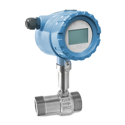
Liquid flows through the turbine housing causing an internal rotor to spin. As the rotor spins, an electrical signal is generated in the pickup coil. This signal is converted into engineering units(Liters, cubic meters, gallons etc.)on the local display where is applicable. Optional accessory modules can be used to export the signal to other equipment.
Flow / Air Velocity / Flow Transmitter / Air Volume
FFM05
Liquid Turbine Flow Transmitter
Products Specification
Measured value:Flow rate, Volume flow
Medium:Liquid:Water;Diesel, etc.(without impurity, low viscosity, flow conditions similar to EN 29104)
Temperature:+10 … +30°C / +50 … +86°F
Output:Pulse, 4 … 20 mA(Option:Local display+4 … 20 mA)
Accuracy:0.5% of rate(Optional:0.2%)
Diameter:DN4 … DN200
Measuring ratio:Standard-10:1;Optional-20:1
Inlet section:≥10 DN
Operating pressure:1 bar
Installation conditions:Inlet run≥10 DN;Outlet run≥5 DN(Take care that flow sensor is always fully filled)
Flow direction:Forward(Arrow on flow sensor indicates flow direction)
Connection
Thread:DN4 … DN50(External);DN15 … DN50(Internal)
Flange(Optional):ANSI / JIS
Operating conditions
Process temperature:-20 … +80°C / -20 … +150°C
Ambient temperature(All versions):Standard(with aluminum converter housing):20 … +55°C
Storage temperature:-20 … +70°C
Pressure:Thread:63 bar(DN4 … DN15) / 25 bar(DN20 … DN50)
Flange:16 bar
ANSI:150 Ib RF
JIS:10K
Material
Housing:SS304(Optional:SS316)
Flanges:SS304
Rotor:2Cr13(Optional:Duplex impeller)
Bearings and shafts:Tungsten carbide
Display meter:Standard:Polyurethane coated die-cast aluminum
Products Applications
Petroleum / Chemical engineering / Electric power and machinery fields


